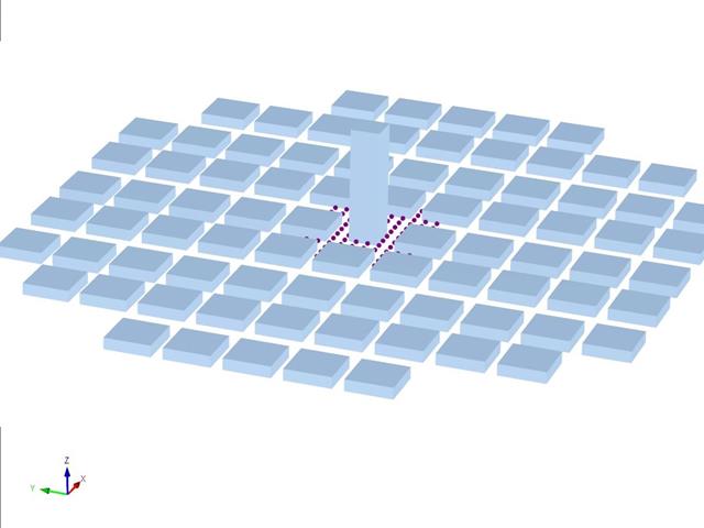
Японский архитектурный институт (AIJ) представил ряд хорошо известных эталонных сценариев моделирования ветра.
В основе данной статьи лежит «Случай E - комплекс зданий в реальной городской зоне с плотной концентрацией малоэтажных зданий в городе Ниигата».
Далее описанный сценарий моделируется в программе RWIND2, а результаты сравниваются с результатами моделирования и эксперимента с помощью AIJ.
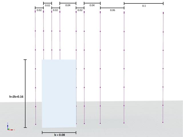
Das Architectural Institute of Japan (AIJ) ставит Рейхе заранее на Benchmark-Szenarien für Windsimulation vorgestellt.
Der Nachfolgende Beitrag dreht sich dabei um den «Случай А - высотное здание формы 2: 1: 1».
Im Folgenden wird das beschriebene Szenario в RWIND2 nachgebildet und die Ergebnisse mit den simulierten und der Experimentellen Resultate des AIJ verglichen.
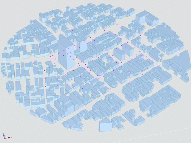
Японский архитектурный институт (AIJ) представил ряд хорошо известных эталонных сценариев моделирования ветра.
Следующая статья посвящена «случаю D - высотное здание среди городских кварталов».
Далее описанный сценарий моделируется в программе RWIND2, а результаты сравниваются с результатами моделирования и эксперимента с помощью AIJ.
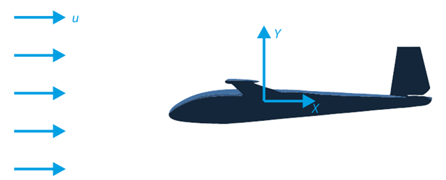
Целью данного контрольного примера является расчёт обтекания планера. Задача состоит в том, чтобы определить коэффициент лобового сопротивления и коэффициент подъёмной силы по отношению к углу атаки. Эти коэффициенты также можно изобразить на графике поляры сопротивления. Предельный угол ламинарного обтекания профиля крыла можно также можно определить по полю скоростей. Доступная 3D-модель CAD (файл STL) используется в RWIND 2.
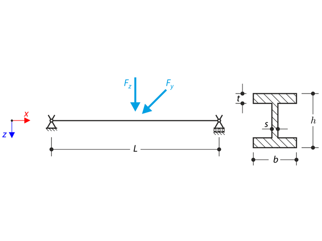
В вилочные опоры затем встроена конструкция из двутаврового профиля. The axial rotation is restricted on both ends while warping is enabled. The structure is loaded by two transverse forces in the middle. The verification example is based on the example introduced by Gensichen and Lumpe.
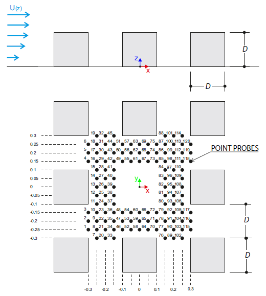
Контрольный пример описывает ветровые нагрузки в нескольких направлениях ветра на модели группы зданий. The model consists of eight cubes. The velocity fields obtained by the RWIND simulation are compared with the measured values from the experiment. The experimental data are measured using a thermistor anemometer in the wind tunnel.
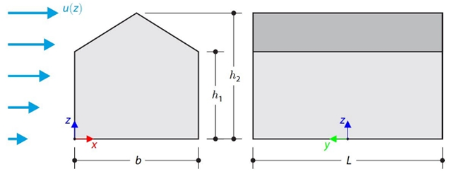
В данном контрольном примере сравниваются расчеты ветровой нагрузки на здание с двускатной кровлей по норме ASCE 7-16 и с помощью CFD моделирования в программе RWIND Simulation. The building is defined according to the sketch and the inflow velocity profile taken from the ASCE 7-16 standard.
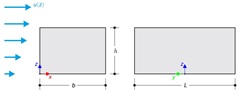
В данном контрольном примере сравниваются расчеты ветровой нагрузки на здание с плоской кровлей по норме ASCE 7-16 и с помощью CFD моделирования в программе RWIND Simulation. The building is defined according to the sketch and the inflow velocity profile taken from the ASCE 7-16 standard.
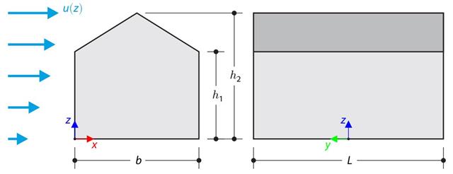
В контрольном примере сравнивается расчет ветровой нагрузки на здание с двускатной крышей по норме EN 1991-1-4 и с помощью CFD моделирования в программе RWIND Simulation. The building is defined according to the sketch, and the inflow velocity profile is taken according to the standard EN 1991-1-4.
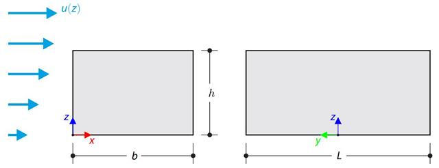
В контрольном примере сравнивается расчет ветровой нагрузки на здание с плоской кровлей по норме EN 1991-1-4 и с помощью моделирования CFD в программе RWIND Simulation. The building is defined according to the sketch, and the inflow velocity profile is taken according to the standard EN 1991-1-4.
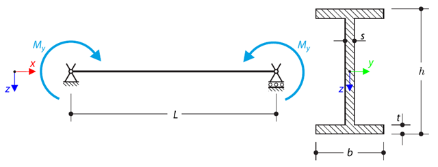
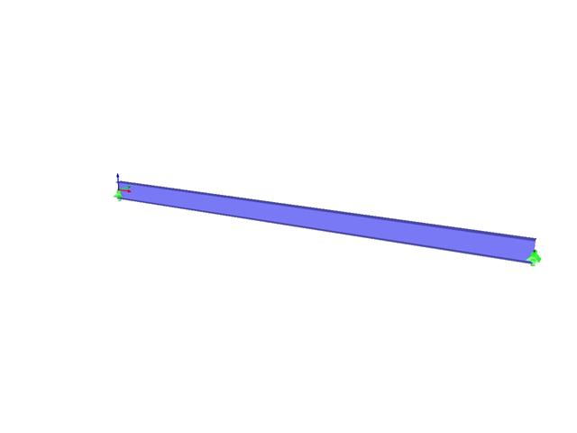
Простая опёртая балка загружена чистым изгибом. Determine the critical load and corresponding load factor due to lateral buckling.
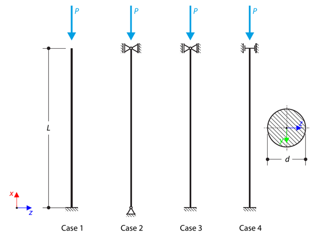
Стойка с круглым сечением поддерживается в соответствии с четырьмя основными случаями потери устойчивости Эйлера и подвергается действию давления. Determine the critical load.
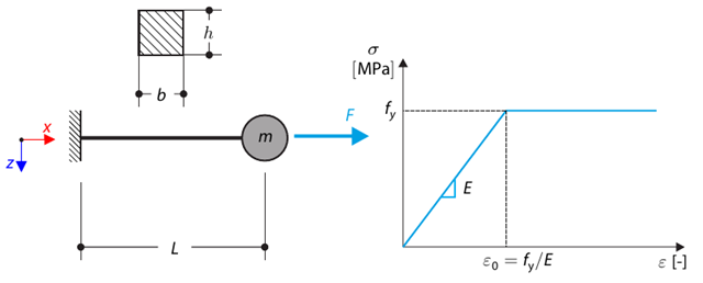
Данный контрольный пример основан на контрольном примере 0122. A single-mass system without damping is subjected to an axial loading force. An ideal elastic-plastic material with characteristics is assumed. Determine the time course of the end-point deflection, velocity, and acceleration.
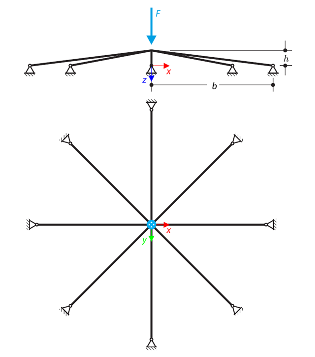
Симметричная конструкция мелкого заложения состоит из восьми одинаковых ферм, встроенных в шарнирные опоры. The structure is loaded by a concentrated force and alternatively by imposed nodal deformation over the critical limit point when the snap-through occurs. Imposed nodal deformation is used in RFEM 5 and RSTAB 8 to obtain the full equilibrium path of the snap-through. The self-weight is neglected in this example. Determine the relationship between the actual loading force and the deflection, considering large deformation analysis. Evaluate the load factor at the given deflections.
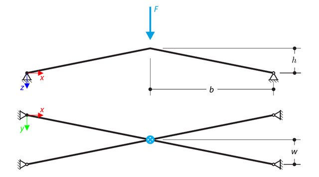
Конструкция состоит из четырех ферм, встроенных в шарнирные опоры. The structure is loaded by a concentrated force and alternatively by imposed nodal deformation over the critical limit point, when snap-through occurs. Imposed nodal deformation is used in RFEM 5 and RSTAB 8 to obtain the full equilibrium path of the snap-through. The self-weight is neglected in this example. Determine the relationship between the actual loading force and the deflection, considering large deformation analysis. Evaluate the load factor at given deflections.
Consider an ASTM A992 W 18×50 beam forspan and uniform dead and live loads as shown in Figure 1. Стержень ограничен максимальной номинальной высотой 18 дюймов (45,72 см). The live load deflection is limited to L/360. The beam is simply supported and continuously braced. Verify the available flexural strength of the selected beam, based on LRFD and ASD.
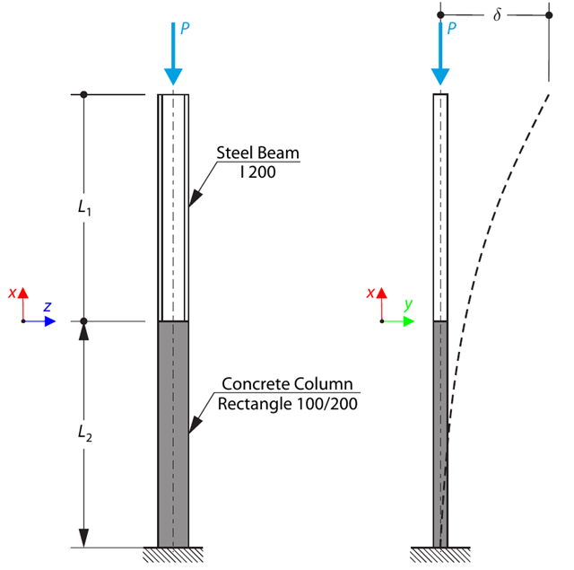
Колонна состоит из бетонного сечения (прямоугольник 100/200) и стального сечения (профиль I 200). It is subjected to pressure force. Determine the critical load and corresponding load factor. The theoretical solution is based on the buckling of a simple beam. In this case, two regions have to be taken into account due to different moments of inertia and material properties.
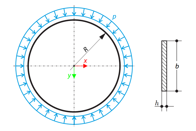
Тонкое круглое кольцо прямоугольного сечения подвергается внешнему давлению. Determine the critical load and corresponding load factor for in-plane buckling.
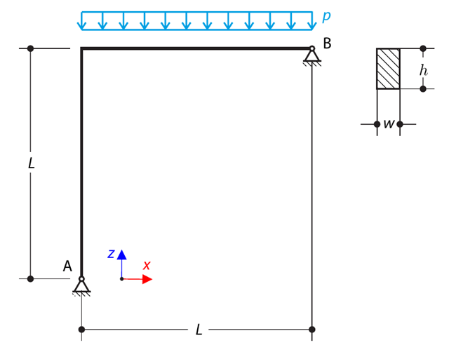
Криволинейная балка состоит из двух балок с прямоугольным сечением. The horizontal beam is loaded by distributed loading. While neglecting self-weight, determine the maximum stress on the top surface of the horizontal beam.
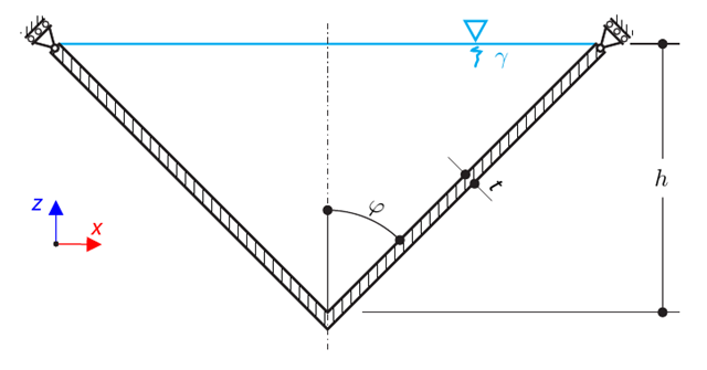
Конический тонкостенный резервуар заполнен водой. Thus, it is loaded by hydrostatic pressure. While neglecting self-weight, determine the stresses in the surface line and circumferential direction. The analytical solution is based on the theory of thin-walled vessels. This theory was introduced in Verification Example 0084.
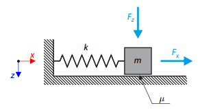
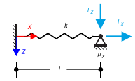
Простой осциллятор состоит из массы m (рассчитываемой только в направлении x) и линейной пружины с жесткостью k. The mass is embedded on a surface with Coulomb friction and is loaded by constant-in-time axial and transverse forces.
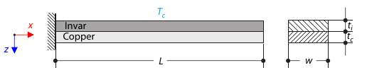
Биметрический пояс состоит из инвара и меди. The left end of the bimetallic strip is fixed, and the right end is free, loaded by temperature difference. While neglecting self-weight, determine the deflection of the bimetallic strip (free end).
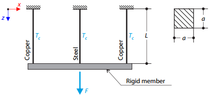
Конструкция фермы состоит из трех стержней (один стальной и два медных), соединенных жестким стержнем. The structure is loaded by a concentrated force and a temperature difference. While neglecting self‑weight, determine the total deflection of the structure.
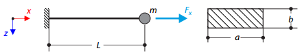
У консоли с прямоугольным сечением на конце имеется масса. Furthermore, it is loaded by an axial force. Calculate the natural frequency of the structure. Neglect the self‑weight of the cantilever and consider the influence of the axial force for the stiffness modification.
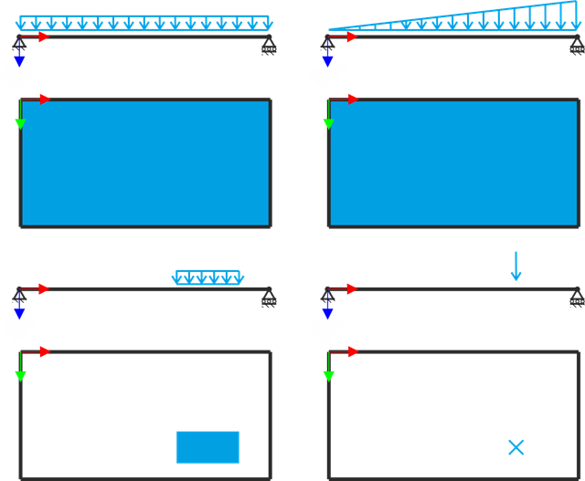
Просто опертая прямоугольная плита подвергается различным типам нагрузок. Assuming only the small deformation theory and neglecting self-weight, determine the deflection at its centroid for each load type.
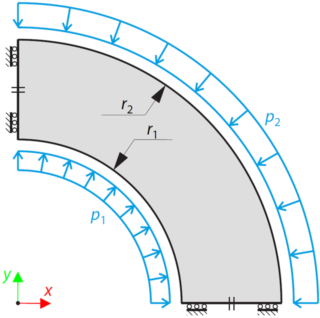
Этот пример является модификацией контрольного примера 0061; разница лишь в том, что материал резервуара несжимаемый. An open‑ended, thick‑walled vessel is loaded by both inner and outer pressure. While neglecting self‑weight, the radial deflection of the inner and the outer radius is determined.
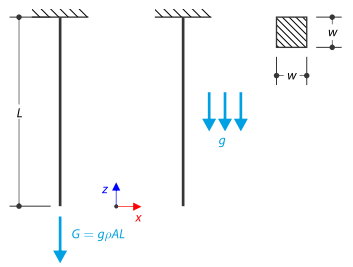
На верхнем конце затем закреплен стержень квадратного сечения. The rod is loaded by self-weight. For comparison, the example is also modeled with the concentrated force load, the value of which is equal to the gravity. The aim of this verification example is to show the difference between these types of loading, although the total loading force is equal.
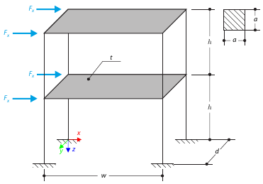
Данный пример служит для демонстрации ограничения диафрагмы. The application is shown on a two-story structure. The structure is loaded by means of lateral forces according to Figure 1. Determine the maximum deflection of the structure ux in the direction of the loading forces using both the diaphragm constraint and the plate model of the floor.
Цель данного примера - продемонстрировать необратимые процессы, вызванные трением. After the loading and unloading, the end-point is in a different position than where it was at the beginning. Determine the movement of the node in the X direction.
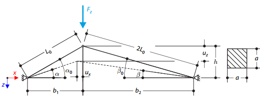
A structure is made of two trusses of unequal length, which are embedded into the hinge supports. The structure is loaded by concentrated force. Собственный вес не учитывается. Determine the relationship between the loading force and the deflection, considering large deformations.